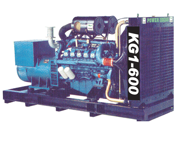
We are Channel Partner of KOEL Ltd. for the sale of Silent Kirloskar Green Make D G Sets through their OEM network in Chandigarh, Haryana, Himacahal Pradesh, J&K and Punjab
We are Channel Partner of KOEL Ltd. for the sale of Silent Kirloskar Green Make D G Sets through their OEM network in Chandigarh, Haryana, Himacahal Pradesh, J&K and Punjab
A. Ground base Foundation (RCC/PCC)
Note: Please ensure that the foundation should not be made over any basement, water tank or Sewer Line.
B. Roof top Installation

| SDG Set rating | Recommended Earth Strip/Cable |
| 5-82.5 KVA | 8SWG-Copper |
| 100-250KVA | 25X3mm Copper/25x6mm GI |
| 320-750KVA | 50X6mm Copper/50x6mm GI 2 runs |
TYPICAL EARTH PIT / STATION ARRANGEMENT
The exhaust system must be designed to keep the resistance to hot gases
(back pressure) as low as possible and load of the extended exhaust pipe / silencer
should not be on the engine manifold
The following may please be noted.
Exhaust pipe load should not come on Expansion bellow and it should not touch
the roof body.
As per statutory regulations, exhaust pipe has to be extended above the
surrounding stack as below.
H= h + 0.2 x kva
Where H = Minimum height of exhaust stack, h= height of building
Exhaust Pipe Details
| Engine Model (Air Cooled) | Minimum exhaust pipe OD (mm) |
| EA10 G1 /EA16 G1 | 50 |
| HA294 G1/HA394TCI G1/HA494TCI G1 | 63 |
| HA694TCI G1 | 76 |
| Engine Model (Water Cooled) | Minimum exhaust pipe OD (mm) |
| 2R1040 G1 | 63 |
| 3R1040T G1/3R1040TA G1 | 76 |
| 4R810TA G1/4R1040TA G1 | 75 |
| 4K1080TA G2 /6K1080TA G2 | 101 |
| 6SL-Series | 138 |
| DV-Series | 150 |
Note-
For 3 Phase
| KVA | 15 | 20/30 | 35 | 45/50 | 62.5/70 | 82.5 | 100 | 125 |
| Al. Cable Size 3.5 core sq.mm | 16 | 25 | 25 | 35 | 70 | 95 | 95 | 150 |
| Copper cable size 3.5 core sq.mm. |
6.0 mm2 |
10 mm2 |
16 mm2 |
25 mm2 |
35 mm2 |
50 mm2 |
50 mm2 |
70 mm2 |
| KVA | 140 | 160 | 180 /200 | 250 | 320 | 400 | 500 | 600/625 |
| Al. Cable Size 3.5 core sq.mm |
185 |
240 |
240 |
2X185 | 2x300 |
2X300 3x240 |
4x240 |
4X300 5x240 |
| Copper cable Size 3.5 core/ sq.mm |
70 mm2 |
95 mm2 |
120 mm2 |
150 mm2 |
240 mm2 |
300 mm2 |
2X185 mm2 |
400 mm2 |
For 1 Phase
| KVA | 15 | 20 | 30-35 | 40 | 50 | 62 | 70 |
| Al. Cable Size 2 core/sq.mm |
35 | 50 | 70 | 120 | 120 2x70 |
150 2x70 |
150 |
| KVA | 15 | 20 | 30-35 | 40 | 50 | 62 | 70 |
| Copper Cable Size 2 core/sq.mm |
25 | 35 | 50 | 95 | 95 | 120 70x2 |
120 70x2 |
Note:-
A. Battery charging procedure
NOTE :-
B. Method to use battery
NOTE :- Battery charger is not supplied with a std. manual Panel. So, it is suggested that the DG set must run once a day for 15-20 minutes so that battery is charged by engine dynamo/charging alternator. Battery should not be kept ideal for 6 months.
C. Precaution to be taken during handling of battery
AIR COOLED
| Engine Model | EA10 G1 | EA16 G1 | HA294 G1 | HA394TCI G1 | H A494 TCI G1 | H A694TCI G1 |
| Lts. | 3.5 | 6.5 | 5 | 8 | 8.3 | 11 |
WATER COOLED
| Engine Model | 2R1040 G1 | 3R1040T G1 | 3R1040TA G1 | 4R810TA G1 | 4K1080TA G2 |
| Lts. | 5.5 | 8 | 8 | 10 | 14 |
| Engine Model | 6K1080TA G2 | 6SL1500TA G2 | 6SL1500TA G3 |
| Lts. | 18 | 27 | 27 |
| Engine Model | DV8TA G1 | DV8TA G2 | DV10TA G1 | DV12TA G1 | DV12TA G2 |
| Lts. | 41 | 41 | 45 | 50 | 50 |
Note:- Recommended K-Oil Premium / Filters Change Interval
| S. No. | Description | Status |
| 1. | Air cleaner mounting | Fitted/Not fitted |
| 2. | Air cleaner cleanliness | Clean/dirty/replaced Dry or oil type) |
| 3. | Air cleaner clamps Hoses | Cracked/normal/not clamped / tightened |
| 4. | Grade & specs of oil used | 15W40 as per koel manufacture's recommendation |
| 5. | Lub oil level & positioning of oil filter | OK/Not OK |
| 6. | Check lub oil safety | OK/Not OK |
| 7. | All Nuts & Bolts | Proper Tightened |
| 8. | Battery condition | Charged/Discharged |
| 9. | Battery Terminal/Leans | Proper/damaged/replaced |
| 10. | Electrolyte level | High/Medium/Low |
| 11. | Fuel Filter | Proper/to be replaced |
| 12. | V Belt for charging alternator | Proper Tightened/not Proper |
| 13. | V Belt tension | Proper/adjusted |
| 14. | Coolant level in the Radiator | High|Medium|Low|filled |
| 15. | Check coolant temp. safety | OK/not OK |
| 16. | Wiring (Engine/Panel) | OK/not OK |
| 17. | Check all wires tightening | OK/not OK |
| 18. | Alternator back cover | Fitted/removed |
| 19. | Cable termination | Proper/loose/Tightened |
| 20. | Canopy door alignment | proper/adjusted/not proper |
| 21. | Canopy door hinge operation | OK/not OK/Adjusted |
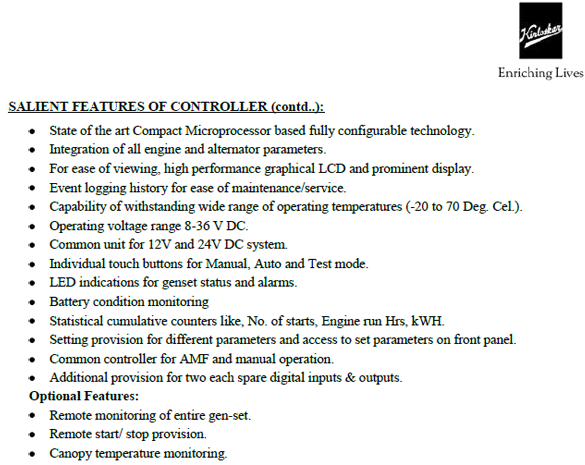
Whenever you want to call a Service Engineer for commissioning, kindly ensure that --
Note:- It is mandatory to get your Diesel Generating Sets commissioned on load and kindly do sign the commissioning report made by our Service Engineer.
Important Note - Trouble shooting points are given just for reference. Please do contact KOEL service dealer for any check or repair.
| Description | Causes | Remedies |
| Engine does not start | No fuel in Tank | Fill Fuel in tank |
| Air in Fuel line | Vent air from fuel line | |
| Choked fuel line | Clean and clear fuel line | |
| Dirty /clogged air cleaner | Check Vaccum indicator, if red ribbon is visible then Clean air cleaner( refer manual for cleaning) | |
| Dirty or choked fuel filter | Contact to KOEL Service Dealer | |
| Faulty fuel Pump | Contact to KOEL Service Dealer | |
| Faulty starter | Faulty starter | |
| Engine used after a long time | Check and Charge battery or Contact to KOEL Service dealer | |
| Battery discharged | Charge the Battery | |
| Loose or dislodged wiring | Check wiring,it should be as per drawing andTightened | |
| Engine needs overhauling | Contact to KOEL Service Dealer | |
| Engine fails to start | Engine used after a long time | Contact to KOEL Service Dealer |
| Engine seized | Contact to KOEL Service Dealer | |
| Engine needs overhauling | Contact to KOEL Service Dealer | |
| Faulty starter | Contact to KOEL Service Dealer | |
| Battery run down/under rating | Contact to manufacturer or Service dealer | |
| Loose or dislodged wiring | Check wiring,it should be as per drawing andTightened | |
| Engine start but stops after some time | Dirty /clogged air cleaner | Check Vaccum indicator, if red ribbon is visible then Clean air cleaner( refer manual for cleaning) |
| No fuel or Low fuel in tank | Fill Fuel in tank | |
| Poor quality of fuel | Change the fuel and use good quality fuel | |
| Air in Fuel line | Vent air from fuel line | |
| Choked fuel injector holes | Contact to KOEL Service Dealer | |
| Dirty or choked fuel filter | Contact to KOEL Service Dealer | |
| Faulty fuel Pump | Contact to KOEL Service Dealer | |
| Water mixed with fuel | Check the reason and sort out or Contact to manufacturer/ KOEL service dealer | |
| Engine seized | Contact to KOEL Service Dealer | |
| Engine needs overhauling | Contact to KOEL Service Dealer | |
| Engine not taking load | Dust entry in air inlet system | Make necessary arrangement to stop dust entry without any modification in air inlet arrangement |
| Dirty /clogged air cleaner | Check Vaccum indicator, if red ribbon is visible then Clean air cleaner( refer manual for cleaning) | |
| High exhaust back pressure | Check Exhaust pipe arrangement, it should be as per manufacturer recommendation,Contact to manufacturer | |
| Derating due to temp,altitide,humidity | Contact to manufacturer | |
| Poor quality of fuel | Change the fuel and use good quality fuel | |
| Choked fuel line | Clean and clear fuel line | |
| Choked fuel injector holes | Contact to KOEL Service Dealer | |
| Dirty/Choked fuel filter | Contact to KOEL Service Dealer | |
| Fuel level setting wrong | Contact to KOEL Service Dealer | |
| Faulty fuel Pump | Contact to KOEL Service Dealer | |
| Water mixed with fuel | Check the reason and sort out or Contact to manufacturer/ KOEL service dealer | |
| Radiator fins choked | Clean the radiator fins | |
| Loose V-Belt | Contact to KOEL Service Dealer | |
| No coolant or level low in radiator | Top up with K Cool super plus | |
| Wrongly adjusted valve clearances | Contact to KOEL Service Dealer | |
| Blown cylinder head gasket | Contact to KOEL Service Dealer | |
| Valve leakage | Contact to KOEL Service Dealer | |
| Broken/worn out piston rings | Contact to KOEL Service Dealer | |
| Worn out cylinder liner & piston | Contact to KOEL Service Dealer | |
| In correct valve & fuel timing | Contact to KOEL Service Dealer | |
| Injector needs adjustment | Contact to KOEL Service Dealer | |
| Faulty governor setting | Contact to manufacturer or KOEL Service Dealer | |
| Engine needs overhauling | Contact to KOEL Service Dealer | |
| Engine speed does not remain constant | Choked fuel line | Clean and clear fuel line |
| Poor quality of fuel | Change the fuel and use good quality fuel | |
| Choked fuel injector holes | Contact to KOEL Service Dealer | |
| Damage or dribbling nozzle | Contact to KOEL Service Dealer | |
| Dirt / choked fuel filter | Contact to KOEL Service Dealer | |
| Faulty fuel Pump | Contact to KOEL Service Dealer | |
| Injector needs adjustment | Contact to KOEL Service Dealer | |
| Faulty governor setting | Contact to manufacturer or KOEL Service Dealer | |
| Load at the time of starting | Start generator at no load | |
| Engin dos not reach governed speed | Choked fuel line | Clean and clear fuel line |
| Dirt / choked fuel filter | Contact to KOEL Service Dealer | |
| Control lever setting wrong | Contact to KOEL Service Dealer | |
| Engine overloading | Ensure Load as per rating or manufacturer recommendation | |
| Excessive smoke at no load or low load | Dirt/clogged air cleaner | Clean air cleaner |
| Damage or dribbling nozzle | Contact to KOEL Service Dealer | |
| Faulty fuel Pump | Contact to KOEL Service Dealer | |
| Engine used after a long time | Contact to KOEL Service Dealer | |
| Wrongly adjusted valve clearance | Contact to KOEL Service Dealer | |
| Blown cylinder head gasket | Contact to KOEL Service Dealer | |
| Valve leakages | Contact to KOEL Service Dealer | |
| Broken/worn out piston rings | Contact to KOEL Service Dealer | |
| Worn out cylinder liner & piston | Contact to KOEL Service Dealer | |
| Incorrect bearing clearances | Contact to KOEL Service Dealer | |
| Damaged main & connecting rod bearings | Contact to KOEL Service Dealer | |
| Incorrect valve & fuel timing | Contact to KOEL Service Dealer | |
| Injector needs adjustment | Contact to KOEL Service Dealer | |
| Faulty governor setting | Contact to manufacturer or KOEL Service Dealer | |
| One or more cylinder not working | KOEL Service Dealer One or more cylinder not working | |
| Engine needs overhauling | Contact to KOEL Service Dealer | |
| Excessive smoke at full load | Dust entry in air inlet system | Make necessary arrangement to stop dust entry without any modification in air inlet arrangement |
| Dirt/ clogged air cleaner | Clean air cleaner | |
| Derating due to temp,altitide,humidity | Contact to manufacturer | |
| Poor quality of fuel | Change the fuel and use good quality fuel | |
| Choked fuel injector holes | Contact to KOEL Service Dealer | |
| Damage or dribbling nozzle | Contact to KOEL Service Dealer | |
| Control lever setting wrong | Contact to KOEL Service Dealer | |
| Faulty fuel Pump | Contact to KOEL Service Dealer | |
| Engine overloading | Ensure Load as per rating or manufacturer recommendation | |
| Worngly adjusted valve clearances | Contact to KOEL Service Dealer | |
| Broken/worn out piston rings | Contact to KOEL Service Dealer | |
| Excessive end play in crankshaft | Contact to manufacturer or KOEL Service Dealer | |
| Worn out cylinder liner & piston | Contact to KOEL Service Dealer | |
| Worn out valves and valves guides | Contact to KOEL Service Dealer | |
| Incorrect valves & fuel timing | Contact to KOEL Service Dealer | |
| Injector needs adjustment | Contact to KOEL Service Dealer | |
| Faulty governor setting | Contact to manufacturer or KOEL Service Dealer | |
| Engine needs overhauling | Contact to KOEL Service Dealer | |
| Engine overheat | Dust entry in air inlet system | Make necessary arrangement to stop dust entry without any modification in air inlet arrangement |
| Fresh Air intek and Hot air discharge not proper | ||
| Gap in radiator and Partition. Hot air recirculation inside canopy | Ensure proper sealing of radiator and Partition | |
| Dirt/ clogged air cleaner | Clean air cleaner | |
| High exhaust back pressure | manufacturer recommendation,Contact to manufacturer | |
| Faulty fuel Pump | Contact to KOEL Service Dealer | |
| Wrong grade of lube oil used | Change the lube oil as per KOEL specification | |
| Dirt/choked suction tube strainer | Clean the tube strainer | |
| Clogged oil passage | Check and clear oil passage, Contact to KEOL service dealer | |
| Radiator fins choked | Clean the radiator fins | |
| Loose V-Belt | Contact to KOEL Service Dealer | |
| Contact to KOEL Service Dealer | Block air passage and ensure no air recirculation | |
| No coolant or level low in radiator | Top up with K Cool super plus | |
| Engine overloading | Ensure Load as per rating or manufacturer recommendation | |
| Wrongly adjusted valve clearance | Contact to KOEL Service Dealer | |
| Prolonged oil change period | Contact to KOEL Service Dealer | |
| Broken/worn out piston rings | Contact to KOEL Service Dealer | |
| Excessive end play in crankshaft | Contact to manufacturer or KOEL Service Dealer | |
| Engine seized | Contact to KOEL Service Dealer | |
| Engine gives out blue smoke | Wrong grade of lube oil used | Change the lube oil as per KOEL specification |
| Excessive oil in the sump | Check and rectify lube oil level upto High mark only | |
| Engine used after a long time | Contact to KOEL Service Dealer | |
| Broken/worn out piston rings | Contact to KOEL Service Dealer | |
| Worn out cylinder liner & piston | Contact to KOEL Service Dealer | |
| Worn out valves and valves guides | Contact to KOEL Service Dealer | |
| Water mixed with fuel | Check the reason and sort out or Contact to manufacturer/ KOEL service dealer | |
| Excessive fuel consumption | Dust entry in air inlet system | Make necessary arrangement to stop dust entry without any modification in air inlet arrangement |
| Dirt/ clogged air cleaner | Clean air cleaner | |
| High exhaust back pressure | manufacturer recommendation,Contact to manufacturer | |
| Poor quality of fuel | Change the fuel and use good quality fuel | |
| External/internal fuel leakage | Check for any leakage and rectify | |
| Faulty fuel Pump | Contact to KOEL Service Dealer | |
| Engine overloading | Ensure Load as per rating or manufacturer recommendation | |
| Blown cylinder head gasket | Contact to KOEL Service Dealer | |
| Valve leakages | Contact to KOEL Service Dealer | |
| Incorrect valve & fuel timing | Contact to KOEL Service Dealer | |
| Injector needs adjustment | Contact to KOEL Service Dealer | |
| Engine needs overhauling | Contact to KOEL Service Dealer | |
| Mixing of Diesel with lube oil | External/internal fuel leakage | Check for any leakage and rectify |
| Damage or dribbling nozzle | Contact to KOEL Service Dealer | |
| Faulty fuel Pump | Contact to KOEL Service Dealer | |
| Broken/worn out piston rings | Contact to KOEL Service Dealer | |
| Worn out cylinder liner & piston | Contact to KOEL Service Dealer | |
| Incorrect valve & fuel timing | Contact to KOEL Service Dealer | |
| Injector needs adjustment | Contact to KOEL Service Dealer | |
| One or more cylinder not working | Contact to KOEL Service Dealer | |
| Excessive oil consumption | Dust entry in air inlet system | Make necessary arrangement to stop dust entry without any modification in air inlet arrangement |
| Dirt/clogged air cleaner | Clean air cleaner | |
| Wrong grade of lube oil used | Change the lube oil as per KOEL specification | |
| Excessive oil in the sump | Check and rectify lube oil level upto High mark only | |
| External/internal fuel leakage | Check for any leakage and rectify | |
| No coolant or level low in radiator | Top up with K Cool super plus | |
| Broken/worn out piston rings | Contact to KOEL Service Dealer | |
| Worn out cylinder liner & piston | Contact to KOEL Service Dealer | |
| Low Lube oil pressure | Dust entry in air inlet system | Make necessary arrangement to stop dust entry without any modification in air inlet arrangement |
| Loose wiring of sensor controller/connection not proper | Tighten connect as per drawing | |
| Faulty Sensor | Replace sensor | |
| Dirt/clogged air cleaner | Clean air cleaner | |
| Wrong grade of lube oil used | Change the lube oil as per KOEL specification | |
| Dirt/choked suction tube strainer | Clean the tube strainer | |
| Lube oil dilution | Check and Change the lube oil as per KOEL specification | |
| Dirt/clogged lube oil filter | Contact to KOEL Service Dealer | |
| Clogged oil passage | Contact to KOEL Service Dealer | |
| Faulty oil pump | Contact to KOEL Service Dealer | |
| Engine overloading | Ensure Load as per rating or manufacturer recommendation | |
| Prolonged oil change period | Contact to KOEL Service Dealer | |
| Engine needs overhauling | Contact to KOEL Service Dealer | |
| Diesel knocking | Poor quality of fuel | Change the fuel and use good quality fuel |
| Faulty fuel Pump | Contact to KOEL Service Dealer | |
| Incorret valve & fuel timing | Contact to KOEL Service Dealer | |
| Mechanical Knock | Loose component | Check and ensure all component should be tighten. |
| Component fouling with any other component | Check and ensure all component should fitted properly | |
| Worngly adjusted valve clearances | Contact to KOEL Service Dealer | |
| Broken/worn out piston rings | Contact to KOEL Service Dealer | |
| Excessive end play in crankshaft | Contact to manufacturer or KOEL Service Dealer | |
| Incorrect bearing clearances | Contact to KOEL Service Dealer | |
| Worn out cylinder liner & piston | Contact to KOEL Service Dealer | |
| Damaged main & connecting rod bearings | Contact to KOEL Service Dealer | |
| Loose mounting bolts | Contact to manufacturer or KOEL Service Dealer | |
| Loose flywheel/wrong adjustment | Contact to manufacturer or KOEL Service Dealer | |
| Excessive Vibration | AVM pad broken or wrong fitment | Replace if AVM Pad broken |
| Gap between foundation and base frame i.e. foundation level is not proper | Ensure proper foundation. Level should be proper | |
| Fluctuation in load | Uniform load should be on Genset | |
| Faulty governor setting | Contact to manufacturer or KOEL Service Dealer | |
| Loose mounting bolts | Contact to manufacturer or KOEL Service Dealer | |
| Loose flywheel/wrong adjustment | Contact to manufacturer or KOEL Service Dealer | |
| Engine rotates very slowly during starting | Engine seized | Contact to KOEL Service Dealer |
| Battery runs down frequently | Under rated battery | Contact to manufacturer or KOEL Service Dealer |
| Canopy lampt remain in ON positionq | Check and ensure proper use of Canopy Lamp | |
| Faulty starter | Contact to KOEL Service Dealer | |
| Battery of wrong capacity | Contact to manufacturer or KOEL Service Dealer | |
| Loose or dislodged wiring | Check wiring,it should be as per drawing and Tightened |
| Description | Causes | Remedies |
| No voltage from Alternator | Decfective voltmeter | Check voltmeter and replace |
| Short circuit between phases | Check and ensure no short circuit between phases | |
| Neutral earthing short with body earthing | Check and rectify | |
| Power cable faulty | Cehck and replace | |
| Excitation circuit open | Check for loose connection | |
| Incorrect excitation circuit connection | Check for proper connection | |
| Low residual voltage | Check for residual voltage. If residual voltage is less than 2.5V(L-N) field flashing required for few seconds | |
| Grounded excitor field | Check and correct | |
| Rotating rectifier faulty | Check rotating diodes | |
| Fuse in AVR failed | Replace fuses | |
| AVR Defective | Replace AVR | Voltage developed but excitation current is high | Rotating diode faulty | Check rotating diodes and replace faulty diodes |
| Prime mover | Adjust prime mover | |
| Prime mover speed is low | Adjust prime mover speed to rated speed | Low voltage build up | V-Trim pot incorrectly set | Adjust voltage by V-Trim pot in AVR |
| Low prime mover speed | Adjust prime mover speed | Voltage-High | Loose or no connection to 'U' terminals of the AVR | Check and correct |
| Incorrect voltage setting | Adjust voltage by V-Trim pot in AVR | |
| AVR Defective | Replace AVR | Voltage fluctutation | Speed fluctuation of the prime mover | Set the speed of the prime mover |
| Incorrect setting of stability pot | Adjust stability pot in AVR | |
| Leading load power factor | Correct the power factor | |
| Load hunting,fluctuates rapidly | Check and reduce the nonlinear load | |
| High percentage of non-linear load | Rectification, Correct percentage of non linear load | Over loading of Generator | Over loading of generator | Check the load and correct. To be in line with name plate rating |
| Blocking of ventilation passage | Check ventilation and clean passage if necessary | |
| Low speed on load | Adjust prime mover speed | |
| Low load power factor | Reduce the load | |
| Generator operating at very high voltage | Check voltage and adjust | |
| High percentage of non-linear load | Check and reduce the nonlinear load | Excessive vibration and noise | Poor alignment | Re-align properly |
| Coupling and foundation bolts loose | Tighten the bolts | |
| Bearing defective | Replace bearing | Over heating of bearing | Incorrect assembly of bearing | Re-assemble correct |
| Bearing damaged | Replace bearing | |
| Generator does not share KW load proportionately | Prime mover speed droop improperly set | Set prime mover speed properly,Droop ( Governor) characteristic of engines. | Generator does not share KVAR load proportionately | Quadrature droop incorrect | Set quadrature droop correctly by QDC Pot in AVR |
| QDC-CT Polarity reversed | Interchange CT secondary | |
| Interchange CT secondary | Check and rectify |
Engine does not start by turning the starting key/push botton provided on panel.
Engine does not start from the AMF panel in any mode.